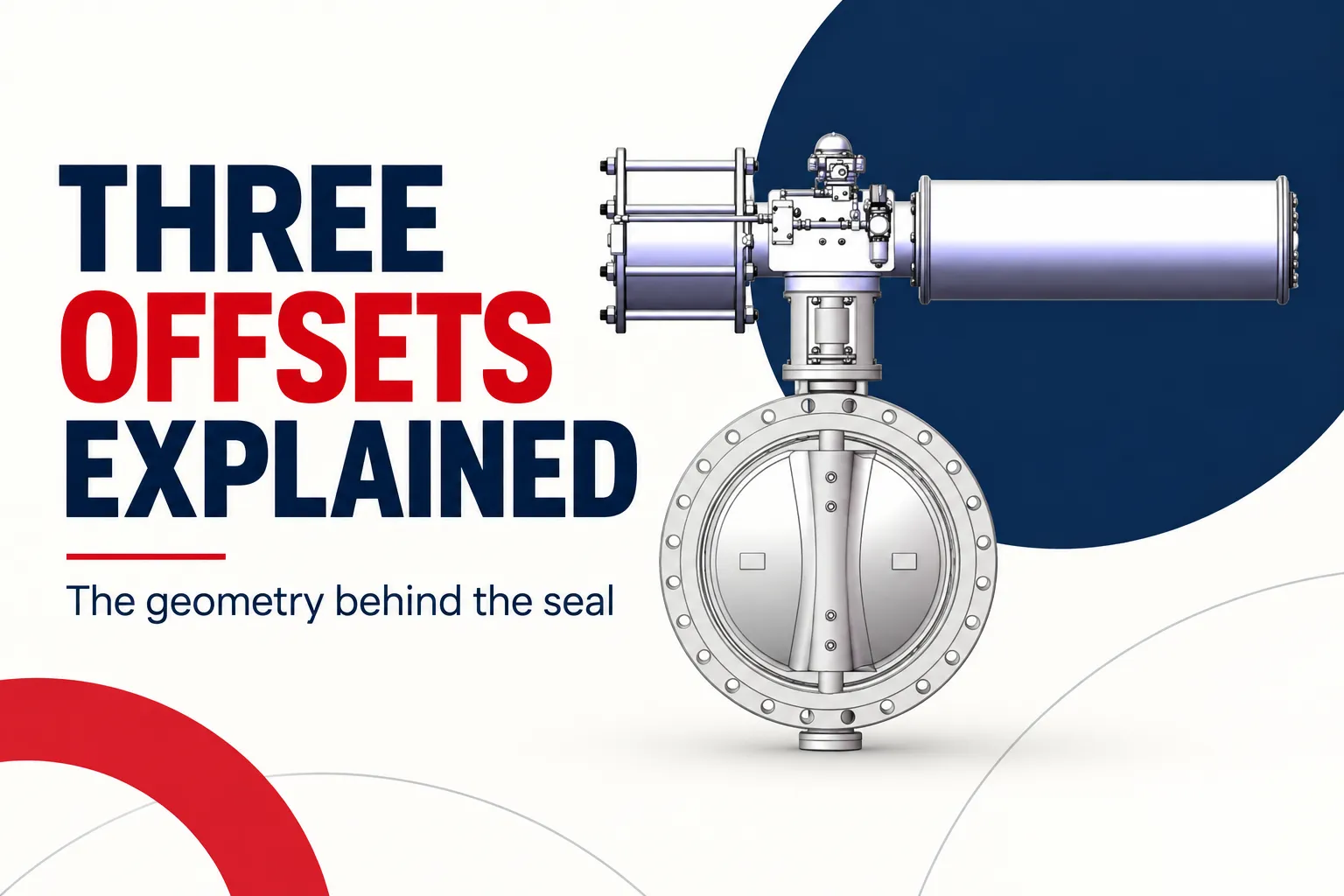

Triple offset butterfly valve design uses three geometric offsets to control how the disc moves into and away from its sealing surface. Two offsets reposition the shaft relative to the pipe centerline and sealing plane. The third changes the sealing geometry, commonly through an inclined conical arrangement. Together, they allow the sealing surfaces to disengage during opening rather than rub continuously through the full rotation.
That geometry is useful because a butterfly valve must rotate a large disc while forming a continuous seal around its perimeter. The design problem is not simply how to turn the disc. It is how to bring two sealing surfaces into controlled contact at closure and separate them without unnecessary sliding during the rest of the movement.
Begin with a centered disc
In a concentric butterfly arrangement, the shaft is centered relative to the disc and flow passage. A resilient seat can accommodate contact as the disc turns into position. This can provide a compact and practical valve for many suitable services, but the contact mechanism differs from the metal-seated geometry typically associated with triple-offset designs.
Imagine closing a circular plate into a surrounding ring. If the plate remains in contact with the ring through much of its rotation, the contacting materials must tolerate that movement. A compliant seat can deform to make the seal. A metal sealing arrangement needs a different strategy if sustained rubbing is to be reduced.
The offsets provide that strategy. They change the path by which the disc approaches the seat, allowing contact to concentrate near the intended closed condition. The exact dimensions and profiles remain specific to the valve design; a simplified explanation should not be treated as a manufacturing drawing.
The first offset moves the shaft behind the sealing plane
One offset places the shaft axis away from the plane of the sealing surface along the flow direction. This changes the motion of the disc relative to the seat as rotation begins. Instead of simply rotating about an axis in the sealing plane, the disc follows an eccentric path.
This repositioning is one part of the separation mechanism. It should not be described as doing all the work alone. The overall contact behavior depends on the combination of shaft location, disc shape, and sealing profile. Removing one feature from that combination would change how the surfaces meet.
When reviewing triple offset butterfly valve design, look for an explanation that connects each offset to the complete movement. Counting three displaced lines on a diagram is less useful than understanding why the sealing surfaces can move apart during opening.
The second offset moves the shaft away from the bore centerline
The next offset places the shaft to one side of the pipe’s central axis. In combination with the first offset, this creates an eccentric, cam-like movement. The disc can move away from its seated contact as it rotates rather than following the same path as a centered disc.
Double-offset valves use two shaft-related offsets and can offer reduced rubbing compared with a concentric arrangement. Their seats and sealing principles still vary by design. It is therefore inaccurate to describe every double-offset valve as having the same material, temperature limit, or leakage behavior.
The comparison is about geometry first. Materials and ratings are additional design decisions. A buyer should not infer the complete operating envelope from the number of offsets alone.
The third offset changes the sealing surface
The third offset introduces an angular difference in the sealing geometry, commonly described using an inclined cone. The sealing line produced at the valve is not simply the edge of a flat circular disc pressing uniformly into a soft ring. The shaped mating surfaces are arranged to contact in the closed position and separate as opening begins.
This is the feature that supports the characteristic nonrubbing opening behavior of many triple-offset designs. “Nonrubbing” refers to the intended seat-contact movement; it does not mean the whole valve has no friction. Bearings, shaft seals, packing, and other moving interfaces still contribute resistance.
Nor does the geometry make every triple-offset valve identical. Seal-ring construction, seat materials, body stiffness, machining, and assembly settings influence the final result. A general explanation of the three offsets cannot establish the exact leakage or temperature performance of a particular model.
|
Geometric feature |
What changes |
Why it matters |
|---|---|---|
|
Shaft offset from sealing plane |
Disc movement relative to the seat |
Helps the disc disengage |
|
Shaft offset from bore centerline |
Eccentric rotational path |
Changes approach and separation |
|
Angular sealing offset |
Mating seat geometry |
Concentrates contact near closure |
|
Complete assembled geometry |
Relationship of all surfaces |
Determines actual sealing movement |
Closing torque completes the seal
Many triple-offset valves use a torque-seated metal sealing arrangement. The actuator must provide the appropriate closing torque to establish the intended contact. Reaching an approximate angular position is not necessarily enough to establish the specified seal condition.
This makes actuator selection and adjustment part of the sealing design. Insufficient closing effort can leave the surfaces inadequately engaged. Excessive effort can impose damaging loads. The correct setting comes from the selected valve and actuator combination, not from a general rule that more torque gives better sealing.
Position indication also has limits. A display can show the configured closed position without proving that the seat meets its leakage requirement. Mechanical travel, applied seating load, and actual sealing performance are related but distinct observations.
Materials determine where the geometry is useful
Metal sealing surfaces can be attractive where the temperature or service conditions exceed the practical range of a chosen resilient seat. However, the complete assembly still contains materials with their own limits. Shaft packing, body gaskets, bearings, and any layers in the seal ring deserve attention.
Thermal expansion can change the relationship between parts. Repeated heating and cooling may be more demanding than operation at one stable temperature. The selection should therefore describe temperature cycles and pressure conditions rather than citing only the highest operating temperature.
For particle-bearing service, consider whether solids can interfere with the sealing contact or damage the surfaces. Reduced rubbing during operation does not make a valve immune to debris. The geometry addresses one contact mechanism; it does not eliminate every possible cause of wear or leakage.
Read design claims in context
A statement about bidirectional sealing, tight shutoff, or high-temperature service should be tied to the actual model, materials, direction, and test basis. It should not be transferred from one manufacturer’s valve to another merely because both use triple-offset geometry.
Yongsheng offers butterfly-valve products that can be considered within this broader design family. When comparing options, separate the geometric principle from the specific assembly’s demonstrated operating limits. That makes the comparison both more accurate and more useful for an application decision.
A practical review can ask three questions. Does the proposed geometry fit the required movement and sealing task? Do the materials fit the fluid and temperature history? Does the actuator establish the intended closed condition within the valve’s mechanical limits? Answering all three is more useful than treating “triple offset” as a complete specification.
Visualize the contact without inventing a cross section
A helpful learning exercise is to separate the disc’s rotation from the shape of its sealing perimeter. First imagine the shaft and disc as a rigid moving assembly. Then consider the stationary seat as a surface the disc approaches only near closure. The offsets change the path between those two objects, so the way they meet differs from a centered plate rotating through a compliant ring.
This mental exercise is deliberately qualitative. It does not establish cone angles, machining tolerances, or the exact contact line for a particular manufacturer. Those details belong to the real design. A simplified diagram is useful only when the reader understands which relationships it represents and which details it leaves out.
The exercise also explains why assembly alignment matters. If the shaft, disc, or seal ring is not in the intended relationship, the designed approach to the seat can change. The actuator may still rotate, but the resulting contact may not be the contact the design requires. Movement alone is therefore an incomplete demonstration of a correctly assembled sealing system.
When reading a product illustration, distinguish the geometric principle from the model’s actual construction. Some images are exterior product views and cannot show the internal seat shape. Others are conceptual schematics. Neither should be used to infer an unlisted material, exact offset dimension, or leakage result. This keeps the explanation useful without turning a visual aid into unsupported engineering evidence.
Frequently asked questions
Does triple offset mean three separate discs?
No. It refers to three geometric offsets in the arrangement of the shaft and sealing surfaces. The valve still uses a rotating disc as its closure member. The offsets describe how that disc approaches and leaves its seat.
Does nonrubbing mean zero operating torque?
No. The actuator still overcomes bearing and packing resistance, fluid forces, and the load needed to establish the seal. Reduced seat rubbing changes one part of the torque requirement; it does not remove all resistance to movement.
Is every triple-offset valve metal seated?
Metal sealing arrangements are characteristic of many triple-offset designs, but the actual construction should be identified from the selected model. Seal rings may have different materials and configurations. Do not infer every component from the design-family name.
Is triple offset automatically better for ordinary water isolation?
Not necessarily. A suitable resilient-seated valve may meet that duty more simply. The value of triple-offset geometry depends on temperature, pressure, medium, operating frequency, and required sealing behavior. Compare the actual service rather than ranking designs by their offset count.
Use the three offsets as a way to understand movement and contact. Then assess the materials, actuator, and tested sealing requirements that turn that geometry into a suitable valve assembly.
References
[1] Bray. Triple Offset Butterfly Valves Tri Lok.
[2] Valmet. Neles Neldisc Metal Seated Butterfly Valves, Series L16, L17, L18 and L26, L27, L28: Installation, Maintenance and Operating Instructions.
[3] Spirax Sarco. Control Valve Characteristics.